


Post Tensioning – Process
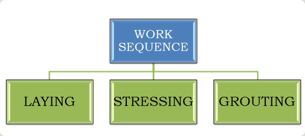
LAYING:
* Completion of formwork as per shop drawing.
* Check level difference; pour strip location, slab thickness and drop panel depth before erection of bottom reinforcement.
* Completion of bottom reinforcement with appropriate Dia of bar and with equal spacing.
* Fixing the block out to casting and wrapping it with OPP tape.
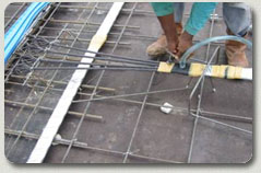
* Marking of tendon in both live and dead end with marker.
* Anchorage should be fixed to the mark at end form work by supporting bars.
* Laying of GI duct is under progress.
* Fixing of duct to end anchorage with the help of vent coupler and it should be wrapped with OPP tape to avoid entry of foreign particles.
* De – coiling of HT Strand and cutting the strand for required size of the tendon.
* Inserting the strands to the duct.
* Check C.G of the casting.
* Bursting reinforcement should be fixed to position at end anchorage
* Profile chair should be fixed to the tendon as per shop drawing.
* Fixing of grout hose in both live and dead end. If the span is more than 35m intermediate vent hose should be provided.
* Proper packing of casting to avoid entry of foreign particle.
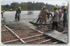
* Pouring of concrete (M-35 Grade).
* Proper vibration of the member @ face of the anchorage.
STRESSING
* Concrete should attain minimum strength of 28N/mm2
* Removal of block out.
* Fixing of wedge Plate and wedges.
* 25% of initial load for slack removal.
* Mark each strand with help of the marker
FLAT TENDON
* Stress the strand for final loading as per stressing calculation report.
* Ensure Protruding strand length is sufficient for stressing (350 – 400mm)
* Stress of tendon is done by (T-25 Jack) as it can stress only one strand at a time.
* Elongation for each strand should be checked after 24hrs.
MULTI TENDON
* Multi jack should be hoisted with chain pulley.
* All strands should be inserted to jack guide pipe.
* Ensure the strand is locked to jack pulling head.
* 25% of initial load for slack removal.
* Record the strand elongation for every incremental of 10 Mpa.
* Release the pressure when the jack has reached desired load.
GROUTING
* Mix the grout as per grout mix.
* The mix is prepared with W/C ratio of 0.4 – 0.45 as per site condition with additive of 0.2% (Weight of the cement).
* Inject the grout from tendon inlet hose.
* As the grout flows out of the intermediate vent, lock these vents in the direction of grout.
* Lock the outlet hose when the grout flows out.
* Check the grout pumped out has the same consistency as its pumped in.
* Lock the inlet hose when the required pressure is achieved (3-5 bars).
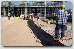
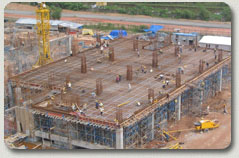
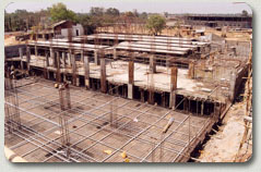
Construction sequence
Bottom shuttering in
progress
Completion of Bottom shuttering
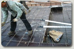
Tying of Bottom Nominal reinforcements

Completion of Bottom Nominal reinforcements
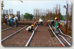
GI Ducts Laying in Progress
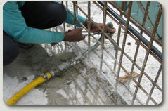
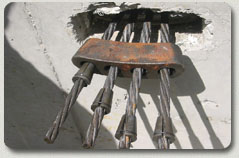
Fixing of ducts at end stressing anchorages
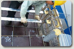
Stressing end Anchorages fixed at Edge RCC Beams
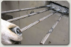
De coiling of HT strands
Inserting of HT strands into GI Ducts
Fixing of bar chairs to form tendon profile
Stressing end anchorage, grout vents on completion of laying
Bursting links at Stressing anchorages

Fixing of Dead ends and Fixing of grout vent
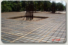
Laying of Tendons on completion

Pour strip provided for construction feasibility
PT Materials
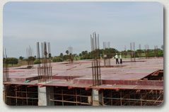
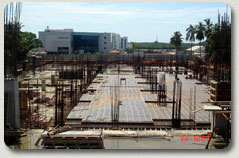
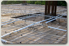
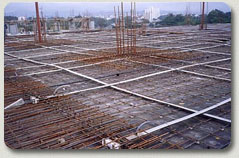
Aerial view of Tendons Laying before concreting
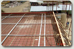
PT Flat slab after completion of Tendon laying ,before concreting
One way PT beam and slab : on Tendon laying completion

PT Tendon Laying in Beam

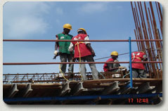
Concreting In Progress
Fixing of anchor Blocks and wedges .
25 % of initial stressing to remove slag.
Stressing Of Slab Tendons. Paint Mark shows Elongation

Paint Mark shows Elongation

Anchorages seen after stressing in edge beams

Excess strand has been cut after stressing

Patching of stressing Pockets

Adding cement in to the mixing tank
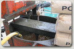
Mixing of Cementicious Grout

Closing of Grout hose end .